| |
Bitmapping a cylinder end

 At
times the need arises for a circular bitmap to be placed
on the end of a cylindrical object and the process tends
to give some Swifters a lot of grief.
In much the same way as bitmaps are placed on square
extrusions, the same is true for round extrusions. Most
commonly the objects are dials, guages or watch/clock
faces. This tutorial is mainly focused on correctly
aligning the bitmap on the material.
If you want to place a bitmap texture on the end of
a cylinder, use this technique and place the extrusion
as a cap on the end of the cylinder. At
times the need arises for a circular bitmap to be placed
on the end of a cylindrical object and the process tends
to give some Swifters a lot of grief.
In much the same way as bitmaps are placed on square
extrusions, the same is true for round extrusions. Most
commonly the objects are dials, guages or watch/clock
faces. This tutorial is mainly focused on correctly
aligning the bitmap on the material.
If you want to place a bitmap texture on the end of
a cylinder, use this technique and place the extrusion
as a cap on the end of the cylinder.
So how do we do it? |
Step
1 - The bitmap
 |
|
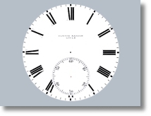
When
using the bitmap of your choice it actually does become
a case of "size matters". The larger the image
and higher the resolution - the better the finish when
rendering. However if the image area is small within
the render, there's no point using large files for,
say, a tiny speed guage on a motorcycle.
The
image on the left is 345x345 px in size and can be downloaded
here.
|
Step
2 - Creating the material
 |
|
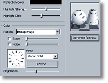
Go
to - Setup > Materials.
Highlight "Bitmap" from
the list and select "Add Material...".
Give your new bitmap texture a Name (e.g. 'watchface'
). In the Finish sub-panel, open the
Ambient Color picker - select white.
In the Color sub-panel, select "Bitmap
Image" from the Pattern drop down
menu. When prompted to select a file - select the watchface.bmp
file. Leave all other settings at their default values!
You
can view the full panel image with all settings required  . .
Hit
"OK" and "Done"
respectively.
|
Step
3 - Creating the object
 |
|
Creating
the object is very simple. One of the improvements of
Version 3 over Version 2 was the inclusion of a selection
of preset shapes in the extrusion editor. By making
use of the preset round extrusion it will speed up the
process of creating our perfect circular object without
the annoyance of all that hit and miss guess work to
get the shape correct. Press the button in the extrusion
editor for 'round extrusion' to create the cylinder. |
Step
4 - Applying and aligning the material
 |
|
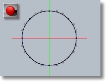
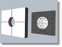
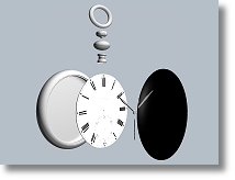
To
understand the way bitmaps are placed onto the surface
of extruded objects in Swift3D, I have created an illustration
on the left of the extrusion editor environment to graphically
help the explanation. The rear object represents the
extrusion editor work area. As seen in the image, this
is how the extrusion editor tiles the bitmap. Placing
an extrusion's centre at 0,0 will make the bitmap seem
to tile. You probably have discovered this already,
rendering after placing a bitmap on an extrusion only
to find the image ending up like a messed up jigsaw
puzzle. |
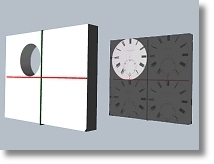 |
|
The front object represents the circle you just created
in the extrusion editor. By remaining in the extrusion
editor and moving the extrusion so it is placed over
the bitmap in one of the four quadrants with its 2 edges
touching the axis lines will produce a correctly aligned
bitmap finish. |
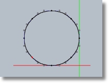 |
|
I chose to move the extrusion left and up as seen
here, so now the extrusion has the bitmap correctly
aligned to it.
Do
not move the extruded object in the main editor to
try and align the bitmap. It simply will not work
that way. It has to be adjusted in the extrusion editor.
|
Step
5 - Sizing to fit
 |
|
Go
back to the main editor.
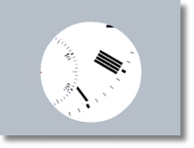
"Hang
on!" I hear you say as you have
eagery hit the quick render button to see how successful
you were - "I have nothing like a
great finish!"
What
you should have is the image shown here. This is because
the bitmap image is too large for the object. To get
it to fit the bitmap you must increase the size of
the extrusion.
|
 |
|
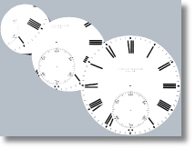
Shown
here are the results of progressively increasing the
size of the extrusion using the Sizing option
from the Properties Menu. The largest
extrusion was the result of increasing the size of the
extrusion by two. It is just fortunate for me that for
this particular project it was exactly the right increase
in size to fit the bitmap! So when sizing up it is a
stepped process of increasing size - checking the fit
and repeating until the extrusion is large enough. |
Step
6 - Completing the scene
 |
|
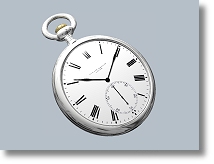
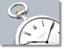
To
complete the scene and put the bitmapped extrusion to
work, I created the watch backing, the glass face, the
winder, and the bottom connector in the lathe editor.
Then they were scaled to fit. The silver knurls on the
winder were a copy and paste of the winder and then
its sweep angle reduced to 5%. I then copy/pasted it
several times around the edge of the winder. The watch
hands were created in the extrusion editor and sized
to fit. The egg shaped sphere was a default sphere with
its height reduced. The torus was also a default torus
with its width widened a little. They were then scaled
to fit. |
Step
7 - Final adjustments and rendering
 |
|
The
final adjustments applied to the image were a default
chrome finish to all the silver parts. A default gloss
black to the hands. A default glass finish to the
glass face. A default gold finish to the winder. I
then reduced the 2 default lights to a grey from the
default white and shuffled them around until the lighting
looked better from the camera angle I was using. I
placed the default grey ripple gradient environment
into the scene. To finish I placed another target
light to illuminate the watch face.
|
|
|


)

